iReal 3D - User Manual
The document aims to provide you a convenient operating manual. Please use the navigation bar or search tool to position your requirements quickly.
Please click
the menu bar at the bottom-leftto show the contents if you browse it on mobile device.
What are 3DeVOK series color 3D scanners?


iReal 2E handheld color 3D scanner, featuring with super large depth of field and scanning area, is designed for medium and large objects and human body scanning. It adopts the infrared VCSEL structured light technology to bring you safe and comfortable scanning experience of invisible light. Without marker points, a quick texture capturing and geometry acquisition can be achieved. Mixed alignment modes meet various scanning situations. With the advantages of cutting-edge algorithm functions, easy-to-use software, ergonomic design, portable and durable, iReal 2E creates an efficient, accurate and rich texture 3D color measurement solution.
The difference between iReal 2E and iReal 2S is that the latter has better scanning details and stronger material adaptability due to blue scanning mode.
What is the structure of iReal 2E?


How it works?
iReal 2E 3D scanner, a device based on the principle of structured light, is composed of 3 VCSEL infrared emitters and a CCD camera. The fixed and coded speckle projected from VCSEL onto a measured item, and CCD camera calculates the spatial position (X, Y, Z coordinates) according to the speckle changes. The point cloud data of the surface contour of the object is obtained for 3D reconstruction.
/wp-content/themes/ireal/assets/

When violating the principle, we can’t capture data that will result in splicing failure.

Recommend Configuration
- Operating system: Win10, Win7
- Processor: Intel I7-8750H and above
- Memory: 32G memory and above (64G is better.)
- Graphics card: NVIDIA GTX1050Ti and above, discrete graphics card 4G and above
- Port: USB 3.0
Please connect the computer to the power supply and set the power mode into high performance when scanning.
Please close firewall and third-party protection software that might cause high-latency scanning.
- The 3D scanner is a precision device, please take it lightly and do not drop it.
- It can be turned on when 3D scanner is connected to the cable, and it will be turned off when the cable is unplugged. There is without separate switch button.
- When 3D scanner is not in use, please unplug and clean up all cables to prevent 3D scanner from falling off caused by tripping, which might damage the device.
- The dongle is a must for the use of device and with high price, please take care of it.
- Please backup the configuration file (3DeVOK SET file) containing the perpetual license.
- Please gently fold the cables along the previous crease when storing it.
- The product is not dustproof or waterproof, so please pay attention to the surrounding environment when using it.
Please click below link to download 3DeVOK Studio scanning software.
Overseas:
China:
Next Cloud
Baidu Cloud Download Code: ir3d
Add Real-time Retract Frame Function
The function helps to delete data that is wrong to alignment. Click undo icon  and select latest data within 100 frames to delete. If you would like to delete the latest 200-frame data, please do the retract function twice.
Add maker holes automatically filled function
Add holes manual-filled function
Add GOM Inspect link
SW adapt to Window 11 system
Add German, French, Spanish, Portuguese and Polish translation
Optimize marker registration function
Optimize the project file saving efficiency
Optimize SW interaction
Open and check user manual under help page
Fix bugs
Software Name
Change from  Real Viewer to
  iReal 3D.
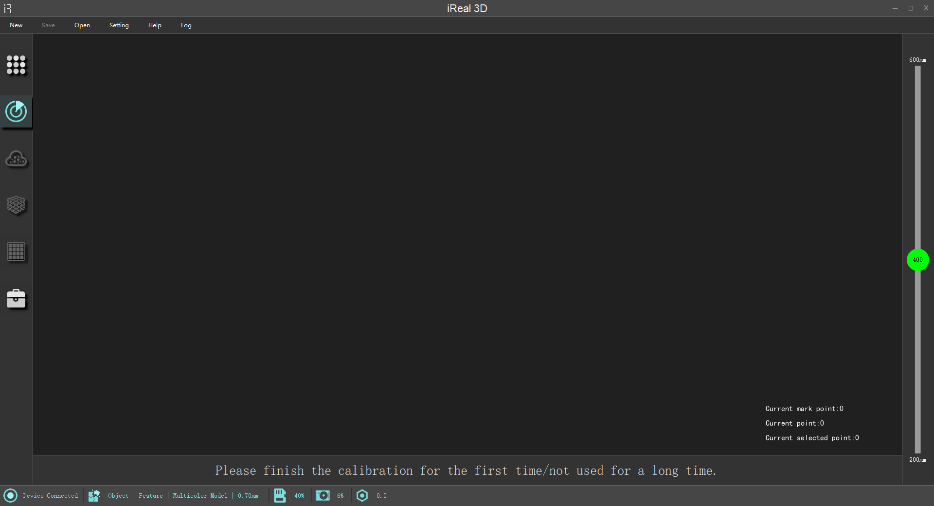
New UI and Interaction Design
UI of this version software has all been upgraded for better and more convenient use. The corresponding interaction logic is also different from Real Viewer, which will be introduced in detail below.
Improve Data Quality
- Optimize the scanning details and support scanning under 0.2mm resolution.
- Optimize mesh processing, mesh details and data quality of object’s edge.
More Friendly and Convenient
Display optimization:
Improve real-time scanning quality and add a new intuitive function – chromatogram display.
Add real-time project file saving:
It supports us to save project file at any time after pausing the scanning.
Features:
- Save anytime.
- Open anytime.
- Continue to scan anytime.
- Scan on site and process at home.
Off-line operation:
Improve the efficiency of on-site operations through using multiple computers to process project files.
Hair scanning enhancement mode: 
Turn on this option to make a clear scanning of hair.
Its principle is to increase scanner’s recognition of thin and black hair. In actual operation, we can use this function to scan not only hair, but also for all hair-like objects.
However, hair enhancement mode is also a double-edged sword. Enhancing the black effect means that it might overexposure to cause low quality data and generate some noise when scanning a white object. Therefore, we should pay attention to turn off the option when scanning some matte objects.
Invisible light scanning mode:
Perform 3D scanning without any visible light to bring you a safe and comfortable scanning experience especially for human body scanning.
Real-time resolution:
We can select certain resolution under the drop-down menu  on the right of “finish” icon
  after scanning.

Different resolutions mean different scanning details.
The closer the scanning distance is and the longer the scanning time is, the better the details.
Compatible resolution:
We can scan it with closer distance and longer time as soon as possible to reach a certain part with high details. After this operation, select 0.2mm resolution before click “finish” icon.
However, how do we know is it ok? Please refer to chromatogram display.
There are default scanning distance ranges under different scanning modes for better work. We can edit it under real-time scanning parameters  according to your custom.
Multi-scene switch:
iReal 3D V3.0 supports multi-scene switch among project interface, point cloud, mesh files, and color mapping because it saves these scanning files in memory. The function helps us get the desired data state quickly while adding some memory consumption.
We can even return to scanning interface after mesh wrapping. It is worth noting that the previous files will be covered after point cloud process and mesh process, which refers to that there in only one kind of data in every interface.
Scanning recovery:
Are you worried about scanning crash or emergencies like power outage? We add this new function to recover project files and keep scanning.
New Functions
Mark points scanning splicing mode:
- Improve accuracy: 0.04mm scanning accuracy is measured by scanning the standard 300mm sphere.
- Explore applications:
- 3D scan castings for reverse engineering and 3D scan items with less features for virtual simulation and 3D
display. - It is used in other situations with the requirements of lower precision.
- 3D scan castings for reverse engineering and 3D scan items with less features for virtual simulation and 3D
- Support mixed splicing mode.
Coordinates straightening: 
Do we need to align the coordinates and then export it before saving the files?
We offer Coordinates straightening we add can be found in tools  and the icon is like this
  . Click the icon to rotate the 3D model to face us and export it. You will find the 3D model is straight in other third-party software.
Note: The 3D model in iReal 3D scanning software is still in statu quo because the model data should be matched with mapping, coordinates. So, it can’t be changed at ease.
Chromatogram display: 
It is on the top bar of tool interface. Scanning data has changed to red and green after starting the function, and red means low quality data and green is high quality data.
Real-time chromatogram display allows users to check the data quality clearly and scan again with closer distance and more times for those low-quality data to ensure the data is with high details and integrated.
See chromatogram display for more details.
White balance: 
When there is abnormal for colorful texture scanning, we can find calibrate interface  and click white balance icon
  to calibrate it. Take out the calibration board and put it on the table, then focus the scanner on the grey card on the left. Press the device button and keep it for 5 seconds to finish white balance calibration.
When having a wrong operation, we can click this  to reset white balance and restart it.
See calibrate process for more operation.
Drop-down menu:
There is an arrow  near the icon of mesh wrapping
  after click “finish”
  , which means other options can be selected. If you ignore it, it will run on the default parameters. At the same time, we can return to re-select when forgetting some operation.
The default parameters are configured through the most commonly used schemes based on a deliberate consideration.
 Finish: The default parameter is the same as the resolution parameter of the scanning mode that you selected. when the scanning mode is selected.
 Wrapping: Closing small holes for human body scanning mode while not closing holes for object scanning mode.
More:
- Close preview.
- Turn off scanning beep.
- Select language.
- Add new scanning mode.
- Set frame rate. It supports us to improve frame rate to have a smoother scanning experience when the configuration of working computer exceeds what we recommend.
- Status bar on the bottom.
iReal series tutorial
Part01 Basic Introduction to iReal 3D Software
part02 Scannig Process
part03 Introduction of Scanning Mode
 3D Scanner
This is the main and precise working device, please don’t drop it.
 Calibration Board
Please handle with care because it’s made by glass.
When the internal structure of the scanner has errors due to external factors, the board is helpful for calibration.
 Marker Points
Marker points are stuck on the surface of those items with less features or the surrounding to help scanning.
 Power Adapter
This product uses 90W input power.
 Cable
Cable
It’s for data transmission.
 Waterproof Box
The outer packing box of this set is for daily store and carry.
 U Disk
- iReal 3D V3.0 Scanning software
- User manual
- Quick guide
- Configuration files
 Dongle
You need to plug in the dongle every time you use the device to scan for the security.
 E-AR Display Module (Optional)
It’s more convenient that the scanning interface can be displayed on the glasses in real time.
Software Installation
- Right-click the iReal3DVX.XX.exe installation package, select the desired language, and click “NEXT”.
- Select installation directory, check “I agree to the License terms and conditions.” and click “INSTALL”.
- Wait for the installation to complete during the installation process.
- Click “Finish” to complete the software installation.
It’s necessary to close third-party protection software before the software installation and the scanning process, which might result in latency.
Software is suggested to install in the disk with large storage space.
Setting of Working Environment
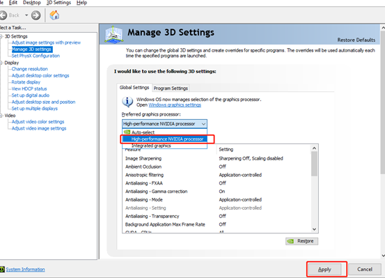
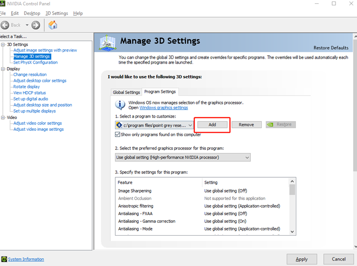
Graphics card setting:
Right-click on the computer desk — Open NVIDIA control panel — Click “Manage 3D Settings” — Click “Program Settings” — Manage selection of the graphics processor — Choose high-performance NVIDIA processor and — Add — iReal 3D.exe — Apply.
How to Connect?
- Connect the device to the USB3.0 of the computer port after plugging in the cable and then turn on the power.

Please turn the arrow mark on the power cord over to the top, align the four thimbles with the power port socket, and then gently plug it in.
- Plug the dongle to USB port, and double-click to run iReal 3D scanning software.
It needs to import the configuration files located in U disk for the first use.
Import Configuration Files
Importing the configuration files is the key to have a normal use of the software and hardware after starting iReal 3D V3.0.
- Insert the USB into the computer.
- The system will prompt you to import the configuration files for the first device connection.

- Click “Yes” to import “iRealSET” files on the U disk.
- There is a prompt informing the successful import and click “Yes” to restart the software.

The configuration file is the third most important thing besides the scanner and calibration board, please keep and backup it properly.
Update Authorization File
When a prompt  appears in the lower left corner of the software, the license status of the device has expired. Please contact your salesperson to obtain the latest license file.
Follow these steps to update it:
- Press right-button to copy the authorization file that normally is
***.RGF. - Find the icon
 of your software
 iReal 3Dand open the file location. - The folder of
iRealSETcan be found. - Press right-button to paste new one to update it.
- Restart iReal 3D software and open Help to check the authorized status.
Calibration
The device should be calibrated before 3D scanning for the first use in order to have a calibration on camera parameters. It needs to be calibrated again in the following situations:
- First use of the scanner.
- Put it aside for long term.
- The device has been shaken or transported.
- Less data is captured for one frame.
- Scanning data can’t be spliced and maker points can’t be recognized.
- Take out the calibration board
which cannot be upside down, and connect the device. Click calibration icon after it shows connected status.
- It comes to the calibration interface, and there are 5 steps to finish it. A calibration video on the right corner is offered to beginners.
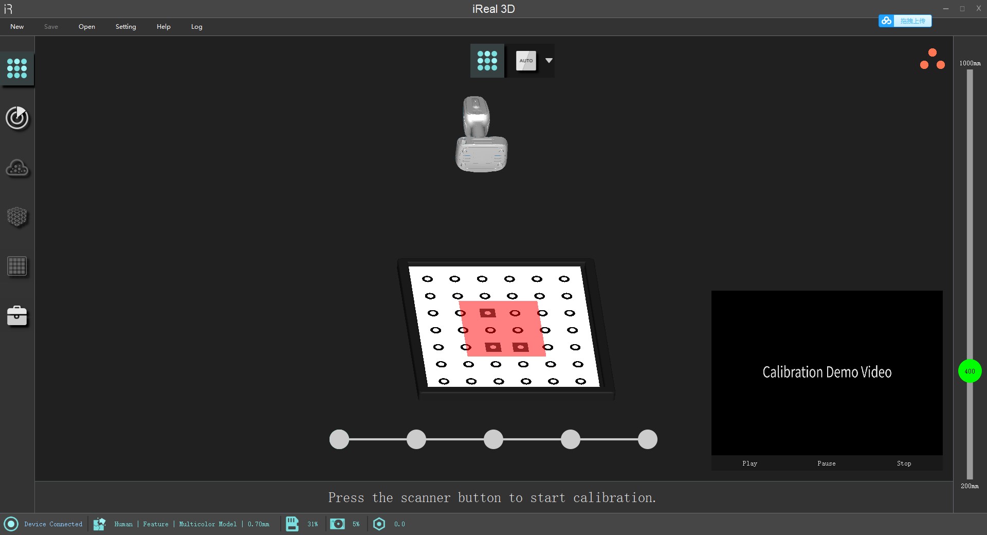
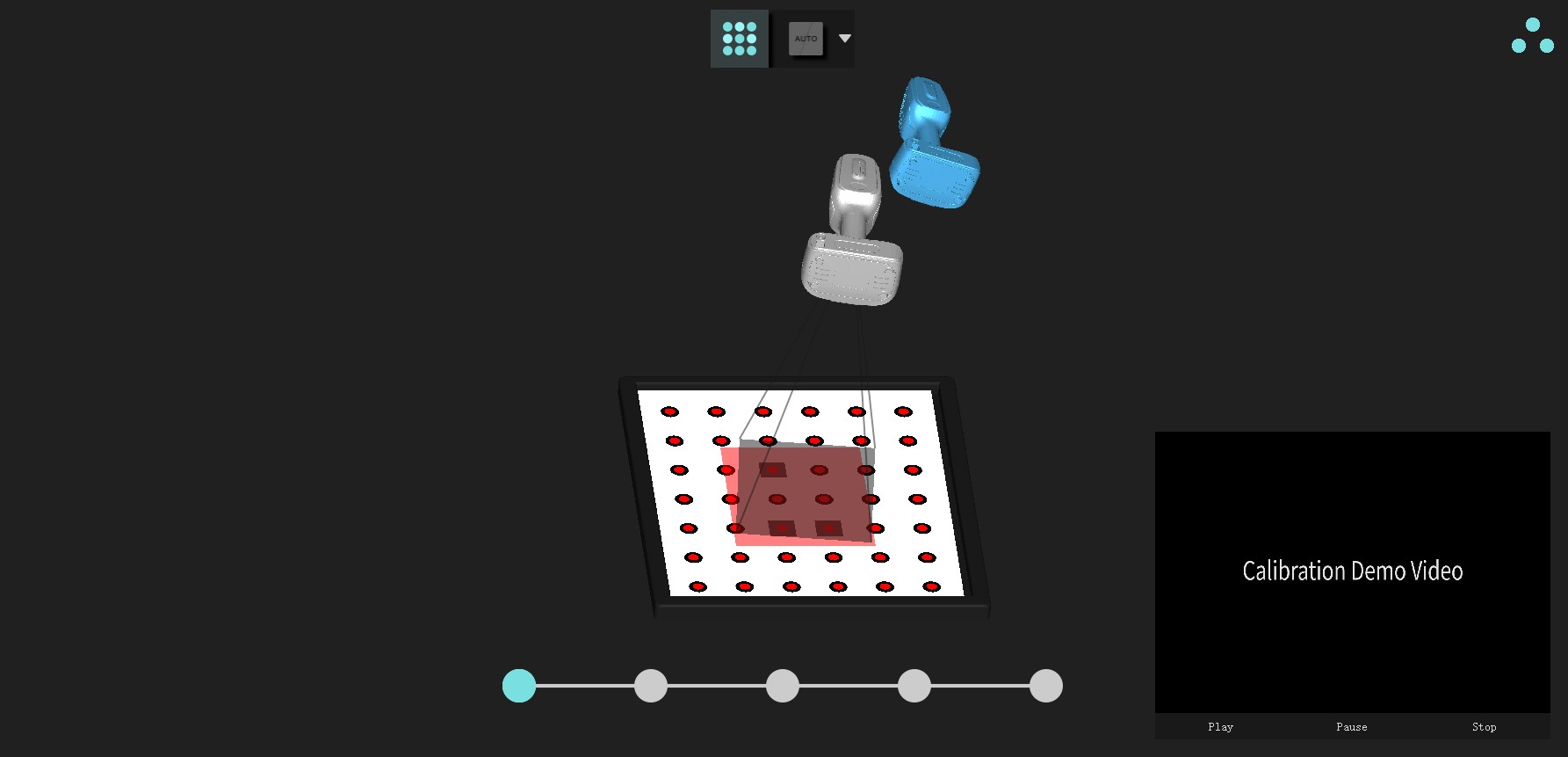
- Move your scanner according to the blue model, and overlap the grey box with the red one as much as possible.
- Finish the calibration.
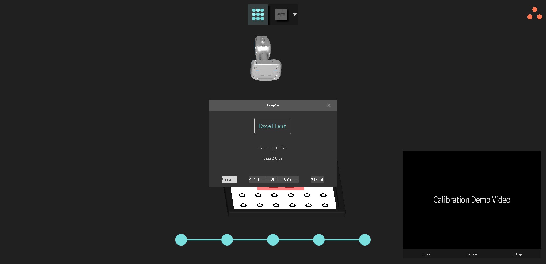
Don’t turn over the calibration board when operating. There isn’t any feedback in the process of calibration when the board is inverted.
The three orange circles represent three cameras of the device. Blue means the camera can capture the markers on the board while orange vice versa. Please adjust the angles to change the color of orange into blue.
There are 5 steps: right above, upper right (inclined), upper left (inclined), upper rear, upper front.
White Balance
It’s not necessary to calibrate the white balance for the first time. The purpose is to calibrate the color standard according to the light environment at that time. Calibration is required in the following situations:
- The color is distorted seriously after finishing the texture.
- When the light environment is particularly complicated like under red light and green light.
- Take out the calibration board and connect the device. Click white balance icon
 to start it.
 - Please focus the scanner vertically on the side of the gray card of the calibration plate, and keep the calibration distance from 400mm to 500mm and stay for 5 seconds. The cross curve of field of view should be located on the center of calibration card or calibration color.
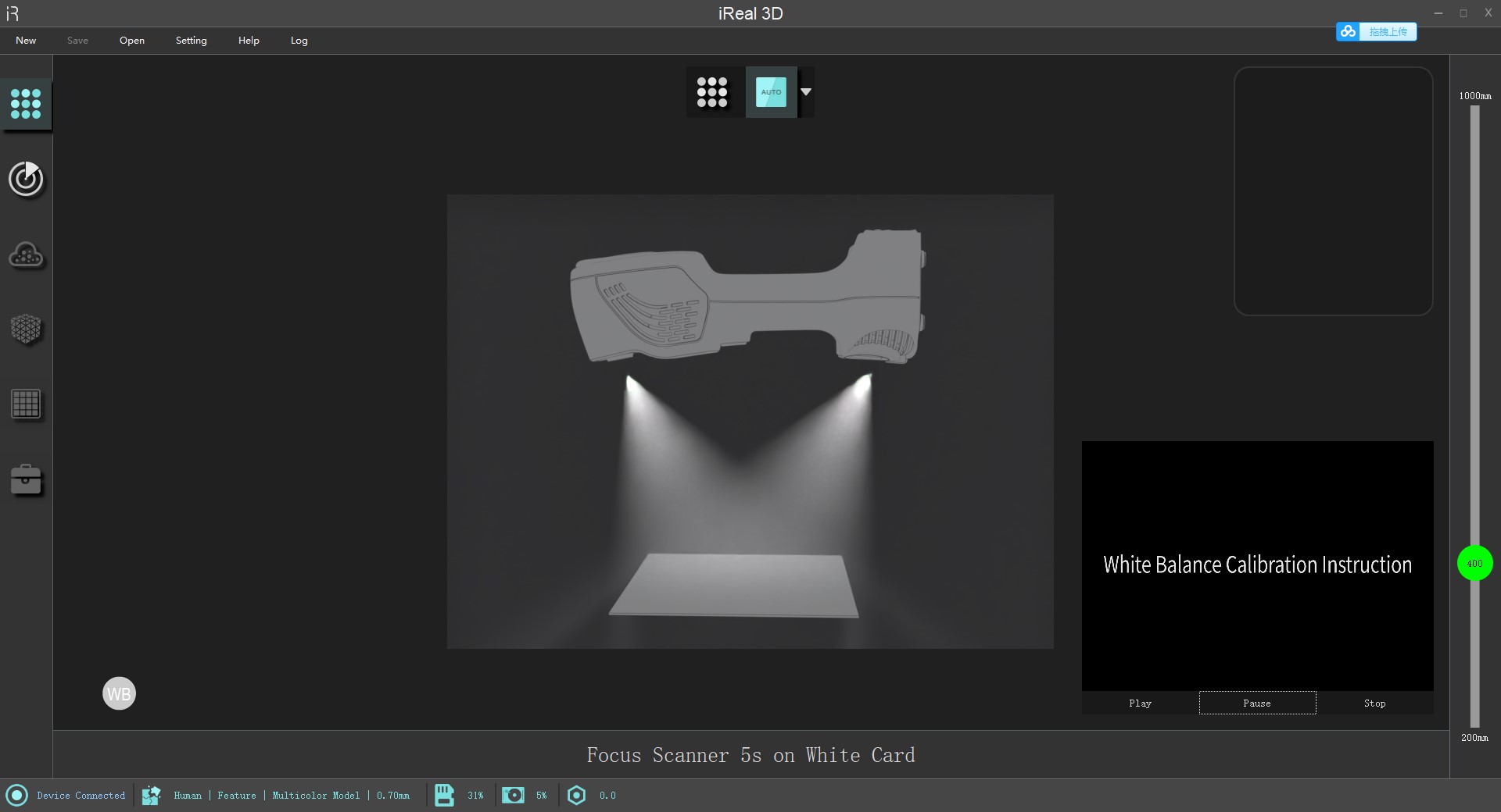
Click the WB icon
to reset if there are any mistakes.
Click the WB icon
to quickly return to factory settings when coming back indoors.
3D Scanning
- Switch to the scanning interface after finishing the calibration. Click the scan icon
 to choose the proper scanning mode.
 - Prepare the scanned item and then press the button of the device to enter into preview. Press again is to pause the preview and press thirdly to start the scan.
- Click the arrow
 near the “Finish” icon
  to choose a certain resolution and then generate point cloud.
Point Cloud Process
Click the icon of point cloud  to enter into the surface. The top tool bar can help you delete the isolated point and disconnected components. Select the way of filling holes to generate mesh data through the arrow
  that is near the icon of mesh
  .
.
There are three ways of filling holes:
Not Close Holes: It means fast saving and not closing any holes, and this kind of file is suitable to import third-party software to process.
Close Small Holes: In human body scanning mode, closing small holes will extend the edge to trim holes while it will trim most of holes in object scanning mode.
Fully Close Holes: All holes will be filled. The filling effect will be not good if trimming the holes that are obviously not able to be enclosed.
Mesh Interface
There are tools such as mesh simplify and mesh refine after clicking the icon of mesh  to enter into mesh interface. Choose whether to smooth the texture and generate it by the arrow
  near the icon of texture
  .
.
Smooth texture will optimize the color and decrease the details.
Texture Interface
Click  to enter into texture interface. The tools include the adjustment of hue, saturation and ambient.
Save
The whole project is divided by 4 modules based on scanning process and each module represents a kind of data and an interface.
- Original scanning data – scanning interface
- Point cloud data – point cloud interface
- Mesh data – mesh interface
- Mesh data with texture – texture interface
This is tools interface which is relatively isolated with scanning process.
The action of saving the file can be carried out at any time that is located in the upper left corner of the interface.

Therefore, what kind of data we want to save depends on what module we have finished and what type of file we want to save.
- Scanning interface:
MK2, scanning project file (.epj) - Point cloud interface:
MK2, scanning project file (.epj), ASC, point cloud project file (.apj) - Mesh interface:
MK2, scanning project file (.epj), ASC, point cloud project file (.apj), STL, OBJ with single color, PLY, SK, mesh project file (.spj) - Texture interface:
MK2, scanning project file (.epj), ASC, point cloud project file (.apj), STL, OBJ with single color, PLY, SK, mesh project file (.spj), OBJ with colors
Open
Open file
Open a single file in the folder such as ASC, STL, etc.
Open project file
Open the index file (.epj/.apj./.spj) under the project file.
File format
- MK2: It’s mark point recognition file which can be recovery when opened again. This file can be saved for next scanning without second-scanning of markers during large-scale scanning work.
- ASC: It refers to point cloud file that records the three-dimensional coordinates.
- STL: It’s a commonly used format for 3D printing that is a polygonal mesh model composed of triangular faces.
- OBJ: Color 3D data generally includes .obj, .mtl, *.jpg.
- PLY: A type of mesh model can usually represent single color or vertex colors.
- SK: Unique mesh model created by iReal 3D can be imported in laser scanning software.
- MK2 files can only be saved after scanning the marker points and then clicking Finish.
- ASC files can only be saved after point cloud data is generated.
- STL and OBJ files can only be saved after the mesh data is generated. Save the OBJ file before mapping and there will be no color.
Project File
It includes three types: scanning project file (.epj), point cloud project file (.apj) and mesh project file (.spj).
Save and open
A folder with the specified name will be saved in the specified location.
The folder is different from ordinary neutral files and includes multiple files.
Click “Open Project File” when opening and find the right *pj file.
The project file supports to be saved at any time during the scanning process.
Its attractive feature is that you can continue to scan after opening it next time and supports offline process.
Point cloud project file
It will be saved in the specified location with specified name.
The folder includes .apj file, .asc file and .textureimage folder.
apjfile
It’s the index file of oping project file.
ASCfile
Ordinary ASC file can be copied and warped to generate as STL file in third-party software. This STL project file can be mapped in iReal 3D, but the premise is that the coordinates have not been modified in the wrap process. 2 ASC project files can be registered in iReal 3D including the texture information.
- TextureImage folder
It saves the texture information that can only be read in iReal 3D. The software will try to map the texture information to the ASC or STL file when opening them though the ASC and STL files aren’t original files.
The greatest function of project files is that they can make data registration between two files.
Mesh project file
It’s same as point cloud project file, which includes spj file that has the same functions with TextureImage and a STL file.
STL file
Ordinary STL file can be used as single-color model for 3D printing, data archives and supporting other third-party software. STL file can also be imported to restoration software and sculpture software to make optimization. The optimized file needs to be saved under the original location and then mapped in iReal 3D.
Mesh project file can support make texture mapping after optimizing the model.
- Don’t rename the OBJ file in Chinese when saving it. The file with Chinese name may lead to mapping loss as it is supported in other third-party software.
- Please select the folder instead of a file when opening ASC and STL project files.
- Don’t rename the project file at will after saving.
Scanning Speed
Although iReal 3D scanner works fast, you cannot scan across it. The right way is scanning the objects from all angles to ensure that the data gets complete and check the chromatographic display at any time.
Otherwise, there may be more data noise and have orange peel phenomenon.
Splicing Missing
Move back to previously scanned area and stay for 2-5s.
The scanned area should have as many features as possible, and the space span should not be too large.
If it has not been retrieved for a long time, you can press the pause button on the hardware first and then aim at the scanned area again to try to recovery it.
Keep the scanned area with rich features to avoid mis-splicing.
Splicing Accuracy
It needs to form a closed loop of scanning path and keep smooth and slow scanning.
Try to scan from the middle to the periphery when scanning medium or large items such as carvings and human body.
Multi-angle scanning will help you obtain more details and higher accuracy.
Hair Scanning
Hair scanning is more difficult because of the fewer features, so we need to align with the help of body parts.
Try to bundle or tie your hair up for the better scanning.
Human Body Scanning
It’s necessary to tell the scanned person to keep as still as possible and look straight ahead before scanning.
Remove the difficult-to-scan objects such as reflective accessories, glasses and watches.
It’s better to keep eyes opened to reduce mending work if 3D data is used for 3D printing or portrait sculpturing.
Keep a stable and fast scanning for body because of avoidable and slight movement.
Have a first scan for those body parts are difficult to keep still and try the best to finish the data capture in one scan.
Extreme poses should be supported by auxiliary tools, such as T pose and A pose.
Please scan the arms at one time because of easy shaking in T pose and A pose.
Body scanning path
Chest – Face – Hair – Chin – Chest – Right leg – Belly – Left leg – Right arm and hand – Back – Right leg – Left leg – Butt – Hair – Left arm and hand.
Texture Splicing
We can make artificial texture to help data splicing when there are not any features.
List of Equipment
Equipment appearance
- Scanner case
- Cameras
- LED light
- Company label
- Shaking to check whether abnormal sound
The accessories in the box
- 3D scanner
- Calibration board
- Data transmission cable
- Power adapter
- 6mm marker points
- Dongle
- USB:Installation package (Check its version), iRealSET configuration file, quick guide and training PPT
Operating status of equipment
- iRealSET authorization > 7 days
- The device indicator turns green
- Successful calibration
- Software connected
Scanning state
- Software version
- High-quality data
- Demo computer
- Computer power cord
- Mouse (Fully charged)
Optional accessories
- Plug board
- HUB
- Spare cable
- Model
- Artifacts
- Product brochure
Scan Settings
Please choose human body scanning mode when 3D scanning human body.
Note: the furthest scanning distance is 1000mm in real-time parameters and open Black Material/Hair Scanning Enhancement Mode in tool bar.
hairstyle

Hairs are difficult to scan as they reflect light in random directions, you can try to apply dry shampoo or mat color spray on the hair to turn them mat.
Or do the post processing with a mesh editor. You can find some library or draw hair using 3DMax, Maya, Blender, Z brush. These kinds of software require advanced skills.
Stay Motionless
- Warn the scanned person to try to keep still and look straight ahead before scanning.
- If having large action during scanning, it will result in overlapping, the failure of data alignment and lots of noise points.
- It’s best to keep the surrounding people quiet because the chatting is likely to make scanned person mood swing and
increase the physical ups and downs. - It’s better to focus on one place if the scanned person opens his eyes as the eye rotation will also drive the body rotation.
Body Pose
- The better pose is the arms against body rather than akimbo posture when scanning the arms. The latter pose requires to scan the inside part that would increase the difficulty and time.
- When scanning the arms or legs with special pose, it is necessary to complete the scan at once and never scan again afterwards because the limb posture is difficult to maintain.
- It’s better to scan close-up fingers instead of opening hands with five fingers as each finger is difficult to capture.
- It could use tools to fix body parts in other body poses like A-Pose and T-Pose, which helps maintain motionless.


Scanning Distance
- Keep the scanning distance within 400mm when face scan.
- We could scan hair with the help of other body parts, so it’s better to keep the distance from 500mm to 700mm for better alignment.
- For other parts, if there aren’t high requirements on them, you can scan with further distance from 450mm to 600mm for fast capture.
Avoid Scanning the Following Objects
- Avoid scanning deformable and floating objects such as skirts, tulle.
- High reflective, mirrored and light-transmitting objects that are difficult to scan like glasses, watches, jewelry, ornaments and black shiny leather shoes.
- Objects that are thin, small, sharp and long.
Scanning Order
- The scan path needs to form a closed loop to increase the feature alignment accuracy, and the whole process should be smooth and fast so that the scanning effect is the best.
- For the parts that are easy to move can be scanned at once, and try to avoid back scanning. For example, the head can be scanned first, then the other parts, and then the subsequent scans do not scan the head again, because the head may be moved with the body action, and the second scan may appear several layers.
- Full body scanning path: start → 1 chest → 2 face → 3 ear → 4 side face → 5 forehead → 6 chin → 7 abdomen → 8-12 left front leg → 7 abdomen → 13-17 right front leg → 7 abdomen → 18-21 right front arm→ 22-23 right arm → 24-27 left front arm→ 28-30 left arm→ 31-34 left back arm → 35-39 right back arm → 40-45 right back leg → 46-51 left back leg → 52-55 back of head → finish

Scanning Parameters
 Light source: blue light iReal 2S and infrared light
 Color: Whether the scanned model carries color, that is, whether the color camera is working. There is colorless in white model.
 Fill light: The photos taken by the color camera are brighter after turning on the fill light. However, the disadvantage is that the fill light is not suitable for patients with epilepsy. Therefore, the default is to turn off the light that can be manually turned on.
 Splicing mode: The working principle of the scanner connection, please see the next chapter for details.
 Situation: The algorithm is different with the changes of situations. No-rigid human body fitting algorithm can make judgements and correct it according to body’s unavoidable and slight movement in human body scanning while it’s not suitable for objects scanning that may cause scanning errors.
 Size &
  Point distance: It is a preset scene and the default point distance is different after scanning depending on various objects size.
Light source and fill light can be edited at any time in the process of scanning, and we can also change the point distance after scanning which will affects the models. See the function of chromatogram display
for more details.
Three Default Scanning Modes
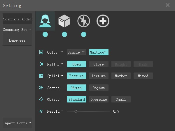
All three default scanning modes have complex algorithmic logic, so customization is not supported.
 Human body scanning mode
The default parameters: color scanning, with fill light, splicing by features, 0.7mm point distance, 280-600 mm scanning distance.
 Object scanning mode
The default parameters: color scanning, with fill light, splicing by features, 0.7mm point distance, 280-600 mm scanning distance.
 LED off model
The default parameters: colorless scanning, without fill light, splicing by features, 0.7mm point distance, 280-600 mm scanning distance.
How to Display and Hide icons?
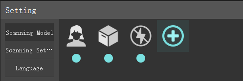
Each blue circle under the icon can be clicked to hide or display the mode icon in main interface.
New Modes
In practice, custom mode is probably the mode we use frequently, so how to add a new custom mode?
- Open setting panel.
- Click the icon of add
 .
. - Select what you need.
- Save it.
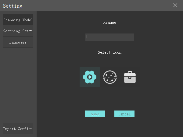
- Name setting.
- Choose an icon.
- Save.
Why need to splice data? It’s not enough to generate point cloud and wrap by imaging in one moment when we scan large objects, which is like putting blocks together. The only way is to capture the whole data of the scanned item while there are several factors such as splicing failure preventing us from scanning smoothly.
If there are rich, irregular and non-repeatable spliceable features in the common area of the two scanned frames Below three feature splicing modes can complete the splicing.
And the point cloud of two frames in common areas may be mis-spliced/un-spliced when there are too few point cloud data/spliceable features.
Feature Splicing
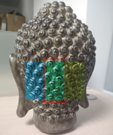
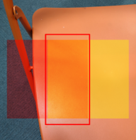
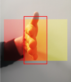
We can gradually complete the scan by precisely matching the data based on the fact that each frame of the scan is different for those scanned objects with obvious geometric features.
Figure 1: Common area with rich features helps have a smooth splicing.
Figure 2: Common area with repeatable features may fail to splicing.
Figure 3: There is a few features that will cause an unsuccessful splicing.
Figure 4: Little point cloud data is a factor of failing to scan.

Texture Splicing
It’s similar to feature splicing and depends on rich variation of patterns.
Marker Points Splicing
Splicing principle:
Reflective marker points are identifiers that the scanner can recognize, which help the device make judgments of the scanned position.
However, a marker point is only identified as a coordinate point in space, and there are many more coordinate points like this that do not constitute uniqueness. Therefore, three or four nearby marker points need to be formed into a geometric recognition with high uniqueness to perform a stable and accurate splicing.
Usage:
- Create a new custom mode as marker splicing mode.
- Stitch the targets on the surface of the surrounding of the scanned item.
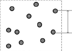
The distance between each two markers is 30mm to 80mm, and it should be determined according to the actual situation. If the curvature of the surface is small, the distance between the markers can be farther, the maximum distance is 80mm. If the curvature of the surface changes greatly, the distance between the markers can be
smaller, the minimum distance is 30mm.
Tips:
When pasting the marker points, try not to paste the obvious features to avoid the loss of key feature data; the more irregular the pattern composed of marker points, the less likely to be misspelled; the pattern composed of three marker points should not become isosceles/ equilateral triangles; try to paste the marker points on different levels, the splicing accuracy will be higher; when scanning the marker points, you need to identify the marker points through different inclination angles (right above, front / back / left / right / slant 45°) to ensure the identification accuracy of the marker points.
- Press the device button to start 3D scanning of markers.
- Finish
 the markers scanning.
 - Press again to scan and generate point cloud.
- Finish
 point cloud capturing.
Demo:
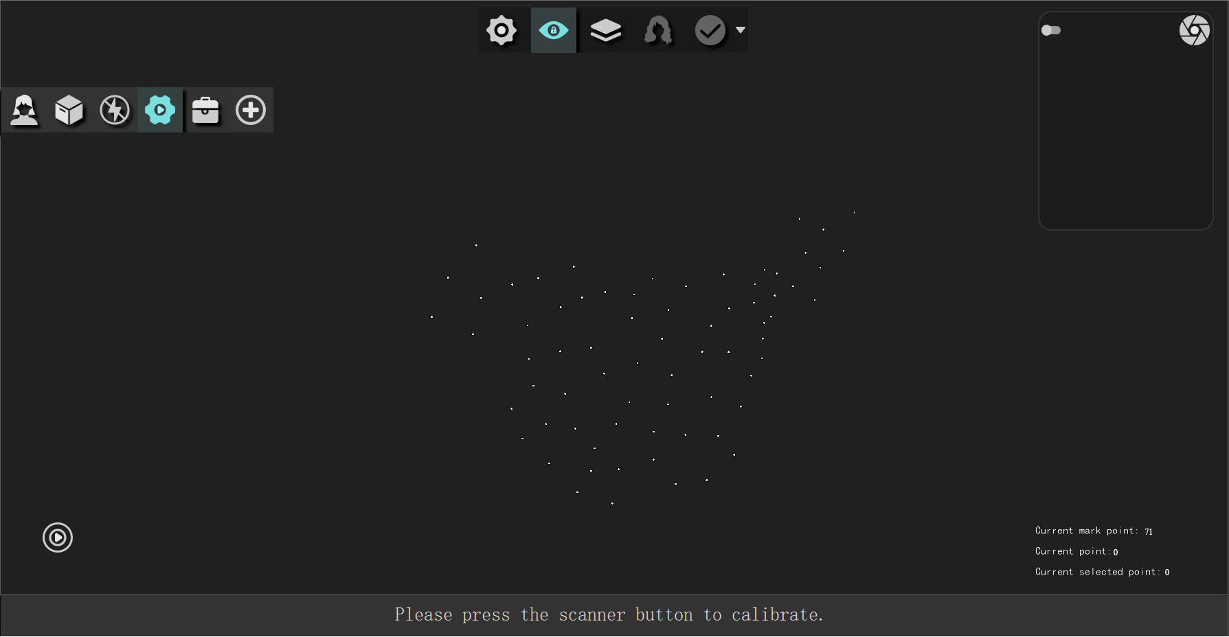
- Press the device button to make a complete scanning of all the markers after pasting marker points on the scanned surface. Stop scanning. Click the Finish button above to realize the precise registration of the marked points, eliminate the wrong marked points to optimize it.
- Press the device button again to scan. 3D data is spliced according to marker point. Stop scanning after capturing all data. Click finish icon and enter into point cloud interface.
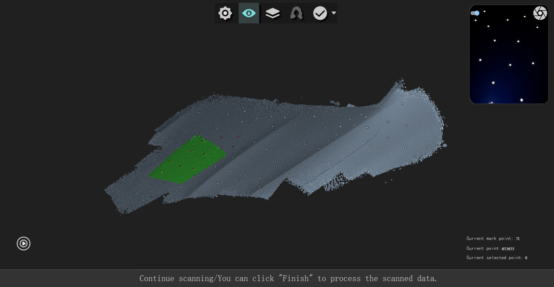
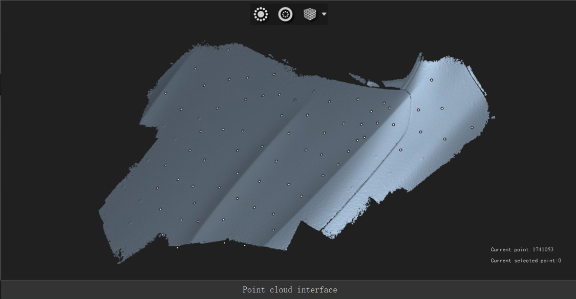
- It can delete isolated point and disconnected components after switching to point cloud interface. Choose certain wrapping mode by clicking the arrow on the right of wrapping icon and generate mesh data.
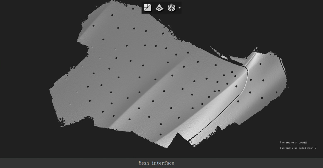
- It can be saved in mesh data interface after wrapping point cloud. The picture below shows the effect of using non-closed holes of the car hood.
Mixed Splicing
The mechanism of hybrid mode adopts splicing of marker points, features and texture with different weights.
Marker point splicing > Features splicing > Texture splicing
Objects that are partially flat, patterned, and feature-rich are suitable for hybrid splicing.
Sticking 4 or more reflective markers in a single frame on a flat part before scanning, smooth data splicing can be carried out. The larger the flat area is, the more markers are stitched.
Chromatographic Display
Real-time and High-resolution Scanning on Parts
Multi-scene Switch
Hair Enhancement Scanning
Invisible Scanning Mode
Feature Value
Prepare:
Prepare two ASC project files that should have large common area.
Process:
- Enter into the tool interface of iReal 3D scanning software and click the icon of model splicing.
- Import two ASC project files respectively and select one to be fixed which means the coordinate system selected will be not changed.
- Select three common points on these two models.
- Click to match them.
- Wrap, texture and save.
If the model is too large, you can use the surface reduction tool after wrapping.
Video
Method 1: Using iReal 3D Software
Prepare
- Save the scanned color model as ASC or STL project file. Take STL file as an example.
- Repairing software like Geomagic, Blender and Zbrush.
Process
- Import the STL file into Geomagic.
- Perform operations such as trimming holes, mesh doctor and de-feature.
- Save copy as STL Binary to replace the original file. If there is a concern, backing up the original STL file is suggested.
- Open iReal 3D and import STL project file.
- Map it.
How to replace STL file and cover color in RealViewer 2.0 and above version?
Prepare:
- One low-quality 3D model including (Hereinafter referred to as low poly.)○ 3D data scanned by iReal device.○ ASC point cloud project file.○ 3D data aligned by 2 point cloud project files.
- One high-quality 3D model including (Hereinafter referred to as high poly.)○ 3D data scanned by laser scanner.○ Sculpturing data in ZBrush.○ Optimized data of a low poly.
- Please note that a dongle is required when opening realviewer 2.6.5 or above version.
Process:
- Wrap the low poly in iReal 3D and save it as STL project file, then a folder is formed including RTImageMessage.asc, text.image and XXX.stl.
- Align the coordinates of the high poly to that of low poly in Geomagic studio, and wrap in Gom Inspect. Please keep the high poly (movement) moving to the low poly (fixed) because the latter one is project file and its coordinates should be accordant with col or information.
- Export the high poly and move it to the folder of the low poly after the coordinates are aligned. Please pay attention to the naming to distinguish the two models.
- Open the high-accuracy model in iReal 3D which will automatically perform mesh optimization and mapping.
- Make appropriate adjustments and export it to OBJ format that can be covered colors.
Method 2: Using Blender or Zbrush or Marmoset Toolbag
Prepare:
- A STL file scanned by iReal 3D
- Several pieces of texture and photos
Process:
- Copy it and then import to Blender. Refine it.
- The refined model is called as low model while its original one is high model.
- Re-topology the low model, unfold UV and then draw the mapping in Blender.
- Perform baked normal map in Marmoset Toolbag after importing high and low model to optimize the details.
- Finish.
Materials
Matte and light-colored objects can be easy to scan the 3D data.
Items with rich colors have better mapping.
The color difference of monochrome items is more obvious.
It needs to spray powder on black, transparent, highly reflective objects to finish the scanning.
Size
The objects with the size of 30cm is better for scanning.
Scanning spray
Scanning spray can be applied on any surface (black reflecting, transparent, etc.) to improve the point cloud data quality.
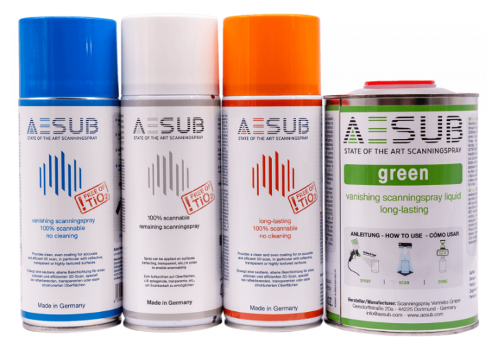
Surface Need to Be Sprayed
Transparent surface:
Such as glass and transparent plastic.
It cannot scan glass since the scanner light will penetrate the glass which makes the camera unable to accurately capture the location of the reflected light. In the case of translucent items, the camera receives insufficient signal from the reflected light to complete the data acquisition. In addition, impurities in translucent objects can affect the reflected light, and the messy reflected light causes the data not to be acquired correctly.
Lenticular material:
For example, jade, ceramic, etc.
The scanner light hits the surface of the object and penetrates inside the object, resulting in the location of the light captured by the camera not being the surface contour of the object, thus affecting the accuracy of the scanned data.
Reflecting material:
Like mirrors, metal processing and highly reflective surface.
The camera is supposed to capture the diffuse reflected light after the scanner light hits the surface of the object, while highly reflective materials such as mirrors produce specular reflection of light because of smooth surface, so that the scanner’s two cameras cannot capture the reflected light at the same time.
Black items:
The light information reflected to the camera becomes less because black items absorb light, which will reduce the scanning speed or cause difficult capture of data.
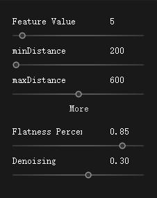
The above parameters can be changed at any time.
Feature Value
Value range: 0-100
Default value: 5
It only effects on splicing mode.
The programmer valued all objects for features to distinguish between strong and weak features. If the value is adjusted to 30, only features that reach the value of 30 will be involved in the splicing while weaker features below 30 will be ignored. Weaker features are easily misidentified to lead to mis-splicing.
Increase this value to avoid data mis-splicing. However, it also improves the splicing difficulty. It can be used in feature or mixed splicing.
Feature value of common objects can be observed in the bottom bar when scanning.

Scanning Distance
See scanning distance for details.
Flatness Percentage
Value range: 0-1
Default value: 0.85
The value of 1 means the flatness accounts 100%.
The higher the value, the less likely it is to be mis-spliced.
De-noising
Value range: -2 -2
Default value: 0.3
When scanning objects that are difficult to scan with black surface, decreasing this value will increase the number of points and accordingly the noise. On the contrary, increasing the value to reduce noise. Although it’s with high-quality data, there are fewer data to be captured. Only when the scanned object is the best material to scan.
Stray colors are involved in the calculation in the camera shot in dark environment during 3D reconstruction, which results in some unwanted deviation values that appear over the surface of the item. Sometimes it is very far away, sometimes it is very close. When it is very close, wrapping point cloud also participates in the calculation to result in orange peel on the surface of the data, and thus the data quality is not high.
The scanner is based on camera imaging, so there is a depth of field issue. iReal 2E has a scanning depth of field of 280mm-1000mm, 720mm in total.
The scanning distance affects the details and splicing. The purpose of this parameter is set up to keep the depth of field within a reasonable range and ensure better detail richness.
The closer the distance, the better the detail. Chromatic display tends to be green, the more difficult the splicing.
The farther away, the worse the detail. Chromatographic display tends to be red, the easier the splicing.
Generally, we will pre-set the best scanning distance in each default mode, but it may not meet everyone’s scanning habits. It can be edited in real-time scanning parameters  .
.
 Chromatogram display is located on the top tools in the scanning interface.
Short-range and long-time scanning helps capture rich details according to real-time resolution and high-resolution scanning on parts.
Observe scanning distance on the right bar to check our scanning distance, then how to know the long-time?
It can select a certain resolution after generating point cloud, see scanning process for details.
Scanning data quality will be presented in different colors after clicking the icon of chromatogram display.
Green refers to high quality data and red is on the contrary.
Suggestion: Don’ t open smart color map when using human body scan mode. This mode is special because human body is easy to move such as breathing that might cause scan errors in the real-time scanning.
The range of chromatogram display various with the change of resolution. The area of green will be decreased under 0.2 resolution while be increased under 1.0 resolution. The reason is that the higher resolution models require more details.
It allows you to have a real-time and clear check of parts with poor data. You can optimize it without professional judgement by performing a repeated scanning with closer distance to turn into green. A perfect and high-quality 3D model is obtained easily.
The richness of the details can be interpreted as the resolution on the 2D picture. The higher the resolution of the same scene, the richer the details.
The deviation value between the scanned model and the actual object is regarded as scanning accuracy.
Frame Rate
Regarding the frame rate, the default of 1Ofps will suit your needs.
If you want smoother stitching and your computer has z6G video memory,you can increase the frame rate to 15 fps.
The faster the scan speed, the more data you getin asingle frame, the better the geometry stitching.


 Quick Enter
 How to Use Scanner?
 Scanning Skills
 Advanced Options
 Terms
Terms