Mesh Files vs. CAD Files: Two Data Formats in 3D Scanning World
11/06/24
In design and engineering fields, mesh files and CAD files are being widely used. As 3D scanning technology develops, more and more real objects are being transformed into digital models, typically in the form of mesh files or CAD files. While both types of files are used to represent 3D shapes, they have distinct characteristics and are suited to different applications.
What is a Mesh File?
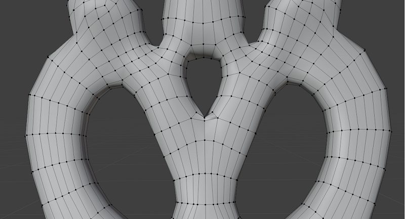
A mesh file is a file format used to represent a 3D object, consisting of a collection of vertices, edges, and faces. Together, these elements define the shape and surface details of the object. The key components of a mesh file include:
- Vertices: Points in three-dimensional space that define the object’s shape.
- Edges: Line segments connecting pairs of vertices, forming the boundaries of the
- Faces: Surfaces enclosed by multiple edges, typically triangles or quadrilaterals, that define the outer surface of the obj
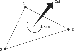
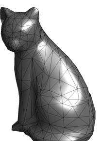
A mesh file is composed of a series of small triangular facets, each defined by vertices and edges. Each triangular facet shares two vertices and an edge with its neighboring facets. Each triangular facet is defined by the coordinates of its three vertices and a normal vector that indicates the direction of the facet’s surface.
The normal direction of each triangular facet is outward. When observing the object from the outside, the vertices are listed in counterclockwise order (as shown in the diagram).
Surface Structure of Mesh File (as shown in the diagram)
A mesh file effectively represents the surface details of a 3D model by using a large number of small triangular facets, which closely approximate the real surface of the model. Common mesh file formats include stl, obj, and others.
Difference between stl and obj Files
Both stl and obj files are commonly used formats for 3D models. stl file describes the surface geometry of a model, typically containing only the normal vectors of vertices and triangles. The file can be in either ASCII or binary format, but neither format includes colors, textures, or other attributes. In contrast, obj file can store more detailed information, such as shape, color, and texture, resulting in larger file sizes. Additionally, obj file is often used in conjunction with mtl and jpg file in 3D modeling, where mtl file defines material properties and jpg file stores textures.
The obj file needs to be coupled with a material (mtl) and a texture (jpg) to represent the color information (as shown in the diagram).
obj files contain the geometric information of a model, such as vertices, texture coordinates, and face data, defining the shape of the 3D model. MTL files are used in conjunction with obj files to define material properties, including color, reflectivity, and texture. MTL files specify the materials required by the obj file. JPG files are typically texture image files used to add details and color to the model’s surface. The texture coordinates (from the MTL file) in the obj file map these JPG images onto the model’s surface. In short, the obj file defines the shape of the model, the MTL file defines the material properties, and the JPG files provide the texture images. Together, these three components create a complete 3D visual representation.
Comparison of stl and obj File Formats
|
stl |
obj |
|
|
Information Included |
Describes only the surface geometry of a 3D object, with no colors, material maps, or other common 3D model attributes. | In addition to the geometric information of the triangular mesh, it also contains the model’s vertices, texture coordinates, face information, normals, and so on. |
|
Type of Information |
Geometric information (shape and position of scanned objects) | Normal information (direction of the scanned object surface) |
|
Commonality |
Both store information about the position of the triangular mesh. | |
|
Difference |
Geometric information defines the basic structure and appearance of an object, but does not include information about how the object reflects or propagates light. | Normal information is used in lighting calculations, shadow generation, and rendering. During rendering, the angle between the light source and observer position and the normal determines how light or dark a surface will be, thus affecting the appearance of the object. (The obj file itself does not contain material information, but it is possible to specify materials and textures for a model by referring to an external material file (mtl file)). |
|
Use |
Quickly represent the appearance of a model for prototyping | Facilitate subsequent rendering |
What is a CAD File?
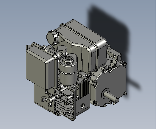
CAD files are a type of files generated by Computer-aided Design (CAD) software for creating, modifying, and sharing accurate 2D and 3D designs. CAD files contain accurate geometric data, dimensions, annotations, material properties, and other information with an emphasis on accuracy, making them suitable for engineering and architectural design. Common formats include dwg, dxf, igs, and stp.
Surface Structure of the stp File (as shown in the diagram)
Comparison of igs and stp File Formats
|
igs |
stp |
|
|
Information Included |
Older format, mainly contains information such as curves, surfaces and volumes | Temporary, containing not only geometric information, but also information on product structure, assembly, materials, machining processes, etc. |
|
Type of information |
Simple geometries and sections | A complete product model, including geometry, topology, and material properties. |
| Data richness | Low | High |
Both igs and stp files belong to the same category, making it easier to convert between the two formats.
Key Differences between Mesh Files and CAD Files
The STP file is fundamentally different from the stl file: the former represents a solid object with precise parameters, while the latter is essentially a mesh. As mesh data, stl files approximate curves using line segments, which can result in distortions compared to the more accurate representation in STP files. To better understand the distinction between stl and STP, consider an analogy with 2D images: stl files are akin to raster images (e.g. jpeg), which consist of pixels with specific colors and positions. When zooming in on a raster image, the pixels simply become larger, making the image appear pixelated and rough. In contrast, STP files resemble vector images (e.g., svg), which are defined by mathematical attributes and can be scaled or modified without loss of quality, maintaining clarity and proportionality.
Comparison of stl and stp File Formats
| stl | stp | |
|
Information Included |
Describes only the surface geometry of a 3D object, with no colors, material maps, or other common 3D model attributes. | Contains richer information than stl files, such as geometry, dimensions, materials, surface properties, assembly relationships, and so on. |
| Essence | Mesh | Entity objects with parameters |
|
Composition |
Triangular Mesh | Mathematical surfaces or solid models |
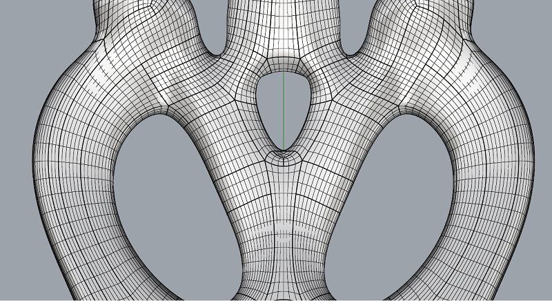
Comparison of the data structure of CAD file and mesh file (the image above shows the stp format, and the image below shows the stl format). Stp is a solid entity with smooth surfaces, while stl is a polygonal mesh (as shown in the diagram).
Applications of Mesh Files and CAD Files
The differences in data structure between mesh files and CAD files lead to distinct applications and use cases. The stl format is commonly used in 3D printing and rapid prototyping, as its polygonal mesh can represent the details and shape of a model, thus enhancing its visuality. As a result, 3D modeling software typically uses stl or obj formats for storing and exchanging 3D model data. On the other hand, CAD file formats contain more engineering-specific information and metadata, such as dimensional tolerances, material properties, and manufacturing processes offering high precision. Therefore, industrial software relies on CAD files for manufacturing and production processes.
Application Range for Mesh Files and CAD Files
| Industrial Software (Rhino, UG, DX) | 3D Modeling Software (3D max,Maya) | |
| Purpose | Obtaining the geometry and structure of an object | Obtain visual properties such as object appearance, texture, material, etc. |
| Modeling Objects | Automobile parts, medical equipment parts, industrial castings | Special effects models, game character models |
| Requirements | Industrial-grade Precision | The appearance, visual effects and artistic expression |
| Data Structure | Complete geometry of objects (geometry, NURBS surface creation, etc.) | Triangular mesh structure (polygon modeling) |
| Formats | stp,igs,sld,prt,dwg | stl,obj |
Conclusions
Mesh files and CAD files play crucial roles in 3D scanning and modeling. Due to the flexibility and adaptability, mesh files can efficiently represent complex 3D shapes and are widely used in fields such as visual effects, animation, and virtual reality. In contrast, CAD files, with their accuracy and standardization, provide a reliable data foundation for engineering, manufacturing and construction. As the two important data formats in the 3D scanning world, mesh files and CAD files differ in the data structure, which makes them suitable for different applications.
Previous: How to Create Seamless Textures in Blender?
Next: What is a 3D scanner?
Related Articles
View Our Product


