Splicing Methods
Quote:
Why do our scanners need splicing? Because the scanned object is usually complex, it is far from the complete reconstruction of the object by only imaging, forming point clouds and packaging in a moment. Just like building blocks, you can’t tell whether it is a cat or a dog by only one block. Only by continuously scanning can the model complete gradually. This process is called splicing.
In theory, we can keep scanning to get a 3D model, but in fact, there are many factors that prevent us from scanning smoothly. For example, when the object is too smooth or too symmetrical, the data alignment will fail under feature splicing.
Learning about the splicing principles may inspire us. For feature splicing, place some crumpled paper under a plant, so that we can smoothly scan the other features.
Let’s learn about the splicing methods of iReal 2E 3D scanner.
Splicing Methods |
Principle |
|---|---|
Feature Splicing |
If the scanned object has obvious geometric features, such as clay sculptures, the scanner can splice accurately according to the point cloud data in each frame. |
Texture Splicing |
It is similar to feature splicing, the scanner can splice according to the rich patterns, like as paintings. |
Marker Splicing |
With the aid of reflective markers, the scanner makes the splicing by identifying their positions in space. |
Mixed Splicing |
The mixed splicing will combine marker splicing and feature splicing together, just weight differently. |
Feature Splicing
Feature splicing is the most commonly used splicing method, which is used in the three default scanning modes. It is very convenient and simple.
However, convenience also means a higher requirement of the Scanning Objects. In this splicing method, splicing failures, and splicing errors often appear. Here are the various situations:
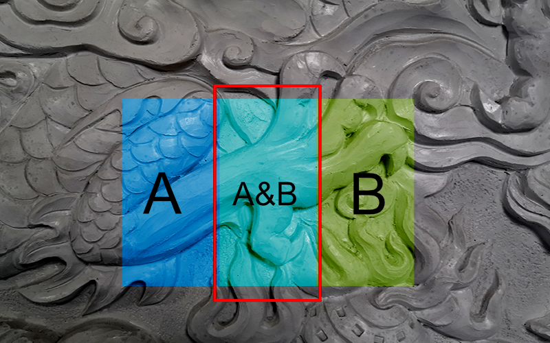
Rich common features, splicing success
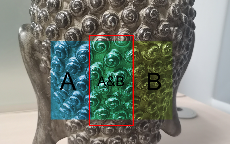
Repeated common features, splicing failure
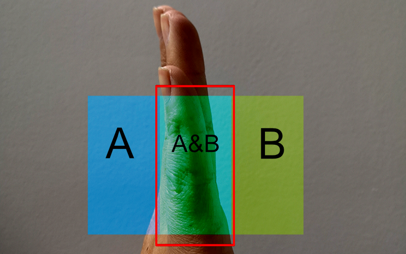
Less common features, splicing failure
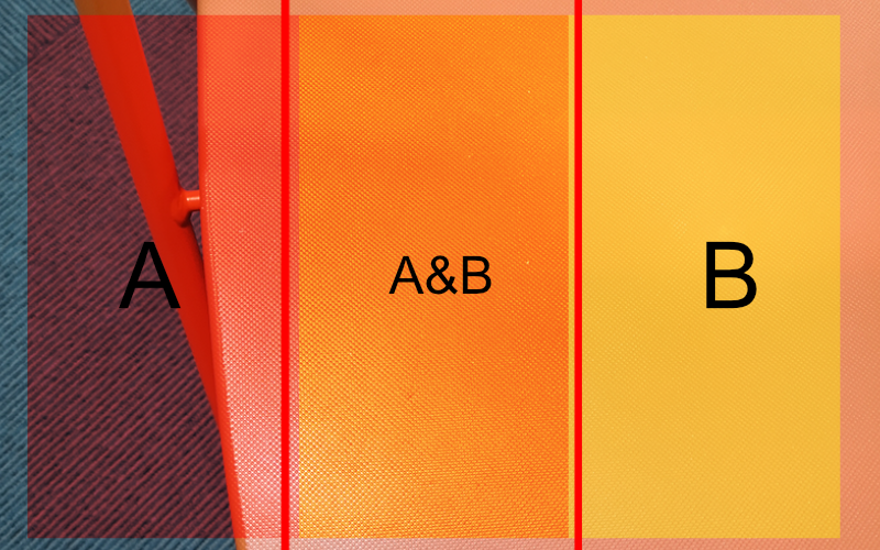
Less point cloud in common features, splicing failure
We should try our best to avoid the above splicing failure, so keep the scanner on the areas with rich features in order to maintain the splicing success status.
Sometimes we want to use feature splicing, but Scanning Objects has no features on its surface. We can use the principles of feature splicing to create some features to help us scan.
Texture Splicing
As the name implies, it is a new way of splicing according to the pattern changes on the object.
If you want to use texture splicing to scan a white paper or fabric, it will fail to do that because of no pattern on white paper and repeated pattern on fabric. Also, texture splicing has lower accuracy than feature splicing, and is easier to be wrongly spliced. So generally we won’t choose texture splicing for scanning normal objects, while we usually use that for scanning paintings.
Marker Splicing
The method of using special black and white circular dots to align data is called marker splicing which is advantageous when scanning objects with few features, and with high accuracy, not easy to have scan errors, and good stability, but we need to remove the markers and the glue will be left on the surface. Therefore, it’s recommended to be used when we need to obtain accurate 3D models, such as scanning car floor mats and industrial parts.
Important
Marker splicing can be used for obtaining 3D models with higher accuracy such as 3D scanning car floor mats and industrial parts.
Markers are not suggested to reuse.
The alignment accuracy is 0.3mm/m under markers splicing.
What is a marker?
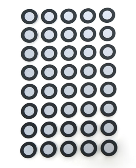
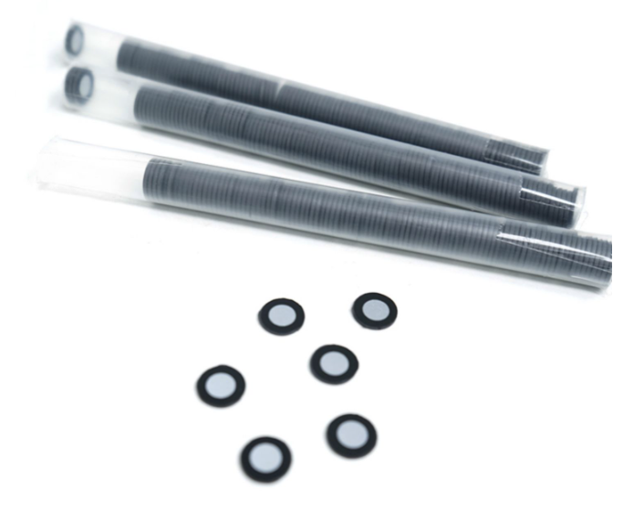
A dot that can be recognized by the scanner is called a marker that is generally round, reflective, etc. The following figures show two of the more commonly used markers: normal and magnetic markers. Please note that the scanner should recognize at least 4 or more multiple makers on a single frame.
Why should I stick so many markers on the object? It can be understood that a single marker is only recognized as a coordinate point in space. There are many such isolated coordinate points, we need three/four adjacent markers to geometric identifiers with high uniqueness. These points can be used for stable and accurate splicing.
Please contact our sales manager to purchase markers officially.
Important
Only see more than 4 markers the scanner will work to splice data.
Various angles are needed to scan the markers to ensure recognition accuracy.
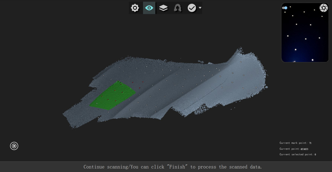
When scanning markers, they will be shown in 4 colors: white, red, green, and blue. White means the markers have been scanned, red means are being scanned, green means the isolated markers, and blue shows markers on the back.
How to stick markers
The distance between the 2 markers is from 30mm to 80mm, which shall be determined according to the actual situation. If the change of surface curvature is small, the distance can be appropriately larger, the maximum distance is 80mm. If there are many features with large curvature changes, the distance can be appropriately narrowed, the minimum distance is 30mm. Note that markers shall be randomly distributed.
Note:
Avoid sticking markers on the area with rich features that will cause the key features to be lost.
The more irregular the pattern formed by the markers, the less likely it is to be misspelled. The pattern formed by three marked points should not form an isosceles/equilateral triangle.
Try to stick markers on the different horizontal planes.
Add New Markers
When scanning, discontinuous scanning sometimes occurs. At this time, we need to add new markers. After sticking new markers on the object, click Add a Marker to continue scanning. However, it is not recommended to use this function in a large area because its accuracy is not high and may cause noisy points if you keep scanning for a long time.
Usage:
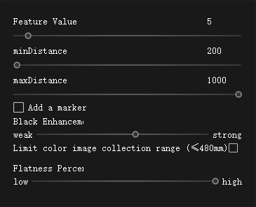
Click Custom Mode , select the marker splicing, and maintain this mode.
Stick reflective marker around Scanning Objects or on the surface. After that, click Add a Marker to continue scanning.
Press the button on the scanner to start scanning the new markers. (No need to scan the other scanned markers)
Press the button on the scanner again to scan the object’s surface.
Scan Demo:
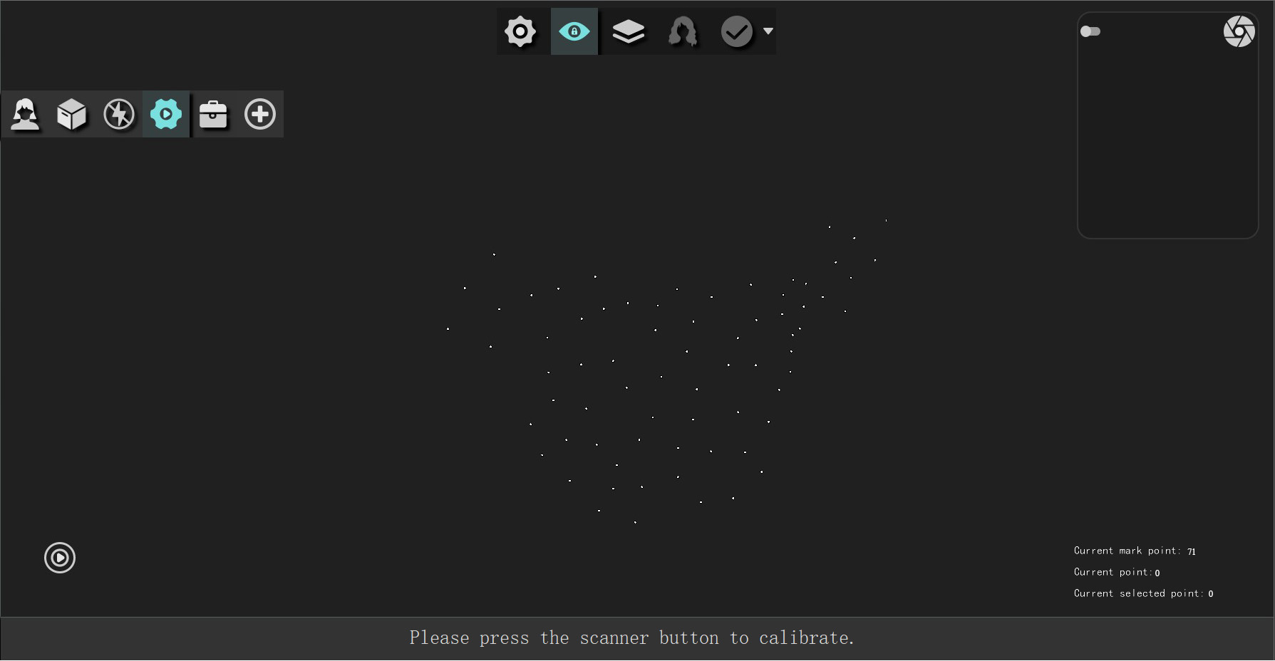
1.After sticking markers, press the button on the object to scan all the markers, and then stop scanning. Click the Finish icon above to achieve fine registration of the markers, it will delete the wrong markers, and optimize them.
2.After scanning markers, press the button on the scanner again to scan the object surface. The splicing is based on the markers. After that, click Finish to process the data into a point cloud. The software will enter the point cloud interface automatically.
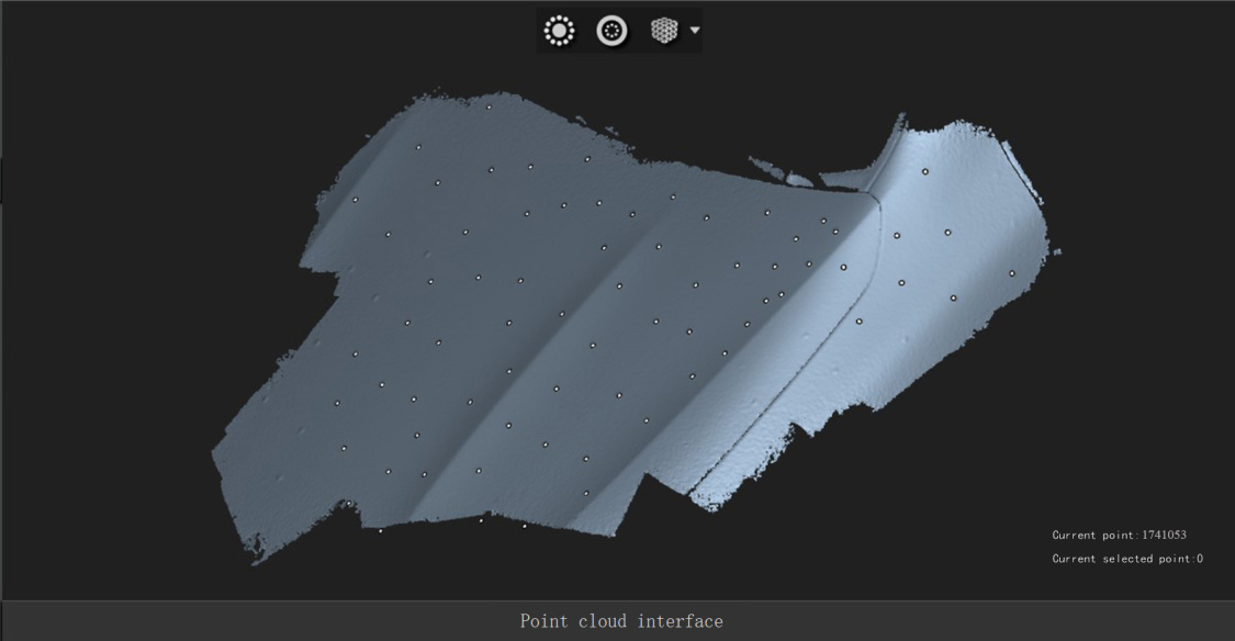
3.In the point cloud interface, there are operation like isolated point and disconnected components. Click the triangle on the right of the wrap icon to select the holes filling mode. Then click the wrap icon.
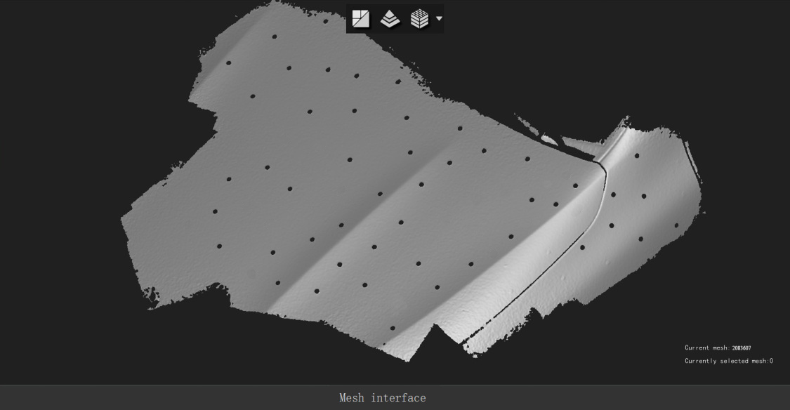
4.After wrapping the point cloud, it enters the Mesh interface. The figure shows the 3D mesh data of the hood with non-close holes. The mesh data supports the function of Measuring girth.
Mixed Splicing
The mixed splicing will combine marker splicing and feature splicing together, just weight differently.
Marker splicing > Feature splicing
The objects with partial flat, patterns, and rich features are suitable for mixed splicing.
When using mixed splicing, cover flat areas in groups of 2 reflective markers. The larger the plane area, the more markers will be sticked.
